HydraFlow® is the latest addition to the UCT’s family of SPE manifolds geared towards efficient sample processing. Its unique design provides enhanced precision and streamlined sample extractions for large volume water analysis

HydraFlow® Features
Enhanced precision and streamlined sample extractions for large-volume water analysis
.
liquid channel switching
Ensures convenient and efficient transition between sample collection and waste discharge.
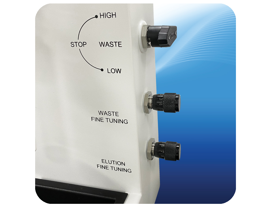
PRECISE FLOW CONTROL
Featured control valves ensure accurate sample flow rates and high reproducibility across a wide range of extractions.
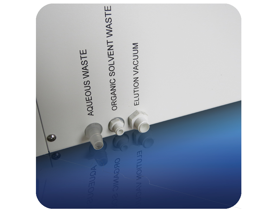
Separation of Organic and Aqueous Waste
Long-term cost savings when it comes to waste disposal.

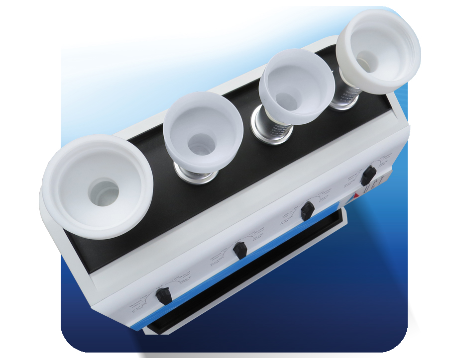
MULTI-sample processing
Four channels can be used individually or simultaneously based on the user preference.
RUGGED ANTI-CORROSION DESIGN
Manifold parts feature PTFE or stainless-steel composition which can resist degradation from prolonged exposure to organic solvents.
Lightweight and Compact Footprint
Simple design allows for fume hood setup if desired and easy relocating when necessary, throughout the lab.
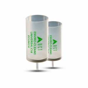
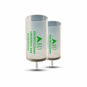
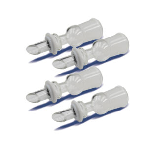
no need for glass cartridge adapters
HydraFlow® does not require the use of expensive glass
cartridge adapters which too often break with use.
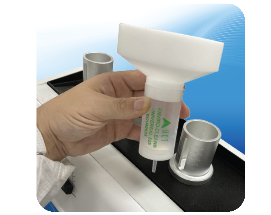
liquid level visualization
Graduated tick marks on Universal cartridge adapters allow for staged liquid-level visualization during an extraction.

EASY ASSEMBLY
Set-up is a simple process, our technical team are available for help and replacement parts are in stock.
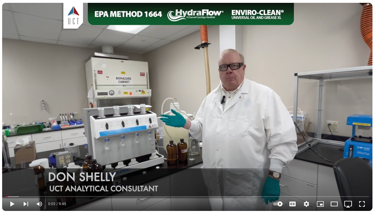
OPERATIONAL INSTRUCTIONS / SPE EXTRACTION
EPA Method 1664 Run on HydraFlow® by Don Shelly
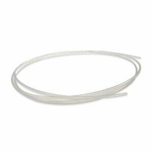
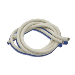
HydraFlow® Replacement Parts
-

-
-
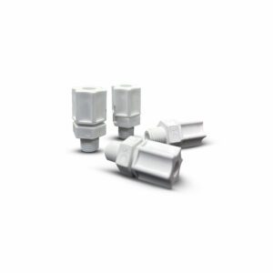
HydraFlow® Metering Valve$249.00
-
-
-
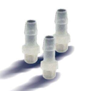
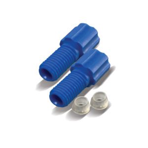
HydraFlow® 3/8″ Barb Fitting$40.00
-
-
-
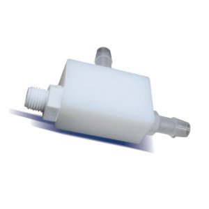
-
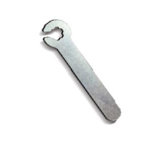
HydraFlow® T Connector$120.00
-
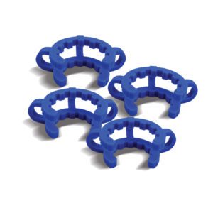
HydraFlow® Clamps$20.00
-
-
-
-
Popular SPE cartridges compatible with HydraFlow®